Contact

Jinye Road, High-tech
Zone, Xi’an, China
Circuit automatic voltage regulator
SVR circuit automatic voltage regulator is a patented product developed by Shaanxi Sefon Electrical Equipment Co.,Ltd.for improving power quality.
After several years of large-scale power grid construction and transformation in rural areas,10kV and rural low-voltage power grids have been greatly improved.Most of the distribution transformers have been replaced by low loss transformers from high loss ones,which improves power supply quality.However,due to the limited capitals for rural power grid transformation,especially the problem of excessive power supply radius in some remote areas,it is impossible to use a large number of high-voltage distribution network points to solve the problem.There are a certain number of long-distance circuits whose power supply radius exceeds the national regulations,it is difficult to guarantee the terminal voltage,the power factor does not meet the requirements,and the circuit loss is large.With the rapid development of China's economy,the majority of rural users have higher requirements for power quality,so it is urgent to improve the power quality.
At present,the measures are taken as follows:
(1)To build new substation.
(2)Adjust the main transformer tap of the substation to change the system voltage.
(3)Reasonably distribute reactive power compensation equipment in the system to improve the distribution of reactive power flow in the power grid.
(4)Change the circuit parameters according to the voltage regulation purpose,and select the cross-sectional area of the conductor according to the allowable voltage loss.
(5)Increase the number of outgoing circuits of the substation to disperse the loss of the original circuit.
Working principle
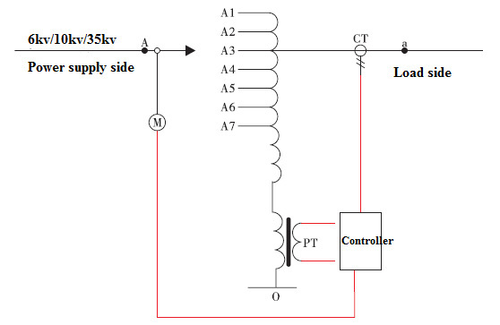
SVR circuit automatic voltage regulator consists of three parts:autotransformer,on-load tap changer and automatic controller.
The whole coil of autotransformer is divided into three parts:series coil,shunt coil and control coil.The on-load tap changer is a switch that can change the contact with load.
Product features
(1)With the structure of autotransformer,can realize on load automatic voltage regulation in the range of+20%.
(2)With excellent control performance and communication function,realizing the"four remote"functions of telemetry,remote signaling,remote adjustment and remote control.
(3)It adopts special interference measures to ensure the normal operation of the controller.
(4)The controller has the function of the highest and lowest gear limit protection to prevent the misoperation in various ways and prevent the tap changer in stuck.
(5)On-load tap changer oil tank is isolated from autotransformer oil tank.
(6)Small volume,large capacity,light weight,easy to install.
(7)It has significant effect of consumption reduction and energy saving
(8)High cost performance,high reliability.
Product information:
SVR circuit automatic voltage regulator
Product profile
SVR circuit automatic voltage regulator automatically adjust the gear of on-load tap changer according to the condition of circuit voltage to realize the change of transformer ratio,so as to ensure that the output voltage is stable in a certain range.It can be widely used in power supply circuit with long distance of power supply,large power supply load,large voltage fluctuation and power quality can’t meet the usage standard.It can also be used in industrial and mining enterprises whose voltage quality can’t meet the production needs.The product has obtained national patent,the patent No.is ZL2010205818.4.
SEFON is a professional manufacturer of voltage regulators in China.Its products are mainly distributed in rural power grid,urban power grid,oil field,coal,metallurgy,chemical industry etc.The voltage regulator has also passed the inspection and acceptance test,and has been operated about 1000 units in electric power companies and oil fields in Shaanxi,Liaoning,Inner Mongolia,Xinjiang,Qinghai,Gansu,Chongqing,Yunnan,Guangdong and others.It is safe and reliable,with obvious pressure regulation effect,and win a good reputation among users.
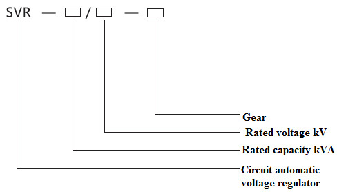
Product model

Configuration&working principle
SVR circuit automatic voltage regulator consists of three parts:autotransformer,on-load tap changer and automatic controller.
The whole coil of autotransformer is divided into three parts:series coil,shunt coil and control coil.The series coil is a group with multiple taps,these taps are parallel connected between the input and output through different contacts of the on-load tap changer to change the tap position,so as to change the transformation ratio of the autotransformer and adjust the voltage.The shunt coil is the common winding of the autotransformer,to generate magnetic field to transfer energy.The control coil provides the working power and sampling signal for controller.
The on-load tap changer is a switch that can change the contact with load.In the automatic voltage regulator,the tap of the series winding is connected to different contacts of the on-load tap changer,and to change the output voltage by adjusting the transformer ratio by change the contact.
The automatic controller is the core part of the whole device.It is mainly consists of single-chip control chip,display circuit,key circuit,voltage sampling,current sampling,status input,communication port,control output circuit,data storage and other circuits.Computer technology and electronic technology are applied,and adopts military grade control chip.It has high reliability,strong anti-interference ability and can adapt outdoor harsh environment.

Product features
●The device adopts autotransformer structure,which has low loss and high efficiency.
●Voltage regulate the width,obvious voltage regulation effect and high accuracy voltage regulation.
●Automatic tracking of circuit voltage change,adjust the gear of tap changer,to realize on-load voltage regulation of voltage regulator automatically.
●It can real-time display the circuit output voltage of the real time voltage,current,current gear,total operation times and daily operation times,set parameters and also can modify the set parameters.
●With excellent control performance and communication function,realizing the"four remote"functions of telemetry,remote signaling,remote adjustment and remote control.
●It adopts special interference measures to ensure the normal operation of the controller.
●The controller has the function of the highest and lowest gear limit protection to prevent the misoperation in various ways and prevent the tap changer in stuck.
●The controller has the function of under voltage protection,over-current protection and daily action limit times.
●With RS232 communication interface,which can realize the monitoring of 30-50m distance through the short-distance wireless module and the remote communication by GPRS.
●On-load tap changer oil tank is isolated from autotransformer oil tank.
●Small volume,large capacity,light weight,easy to install.
●It has significant effect of consumption reduction and energy saving
●High cost performance,high reliability.
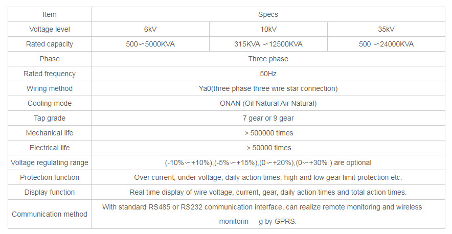
Main technical parameters

NOTES:
●1.The selection of voltage level shall match the circuit voltage level.
●2.The selection of rated capacity is generally 1.1-1.2 times of the total capacity of distribution transformer after the installation point of voltage regulator.
●3.Samples of selection basis of voltage regulation range are as following:
●The voltage at the input end of the voltage regulator is 9-11kv,and the voltage regulation range is-10%~+10%;
●The voltage at the input end of the voltage regulator is 8.66-10.66kv,and the voltage regulation range is-5%-+15%;
●The voltage at the input end of the voltage regulator is 8-10kv,and the voltage regulation range is 0~+20%.
●The voltage at the input end of the voltage regulator is 7~10kV,and the voltage regulation range is 0~+30%
Installation method
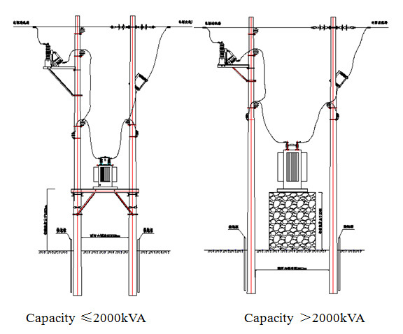
The installation mode is outdoor installation,there are two installation modes.
If the capacity is less than or equal to 2000 KVA,the installation bracket can be used for double pole erection,and if the capacity is over 2000 KVA,the installation base is needed.Refer to the installation diagram as below:

automatic,regulator,voltage
previous page
next page
previous page
next page
Related information


